Computer Graphics
CSE 5280 Course
References
- Computer Graphics Principles and Practice Second Edition, Foley, van Dam, Feiner, Hughes
- HyperGraph from ACM
- Dr. Shoaff's on-line Graphics Course
Physical Input Devices
Locator
I. Tablet
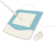
- Flat surface ranging from about 6" X 6" to 48" X 72", which can detect the position of
a movable stylus or puck
- Electrical sensing mechanism composed of grid wires embedded in the table to detect position of stylus
II. Mouse
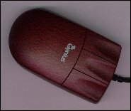
- Invented by Douglas Engelbart of Stanford Research Center in 1963, and pioneered by Xerox in the 70's
- As you move the mouse, the pointer on the display screen moves in the same direction
- Mice contain at least one button and sometimes as many as three, which have different functions depending on
what program is running.
- The mechanical mouse has a rubber or metal ball on its underside that can roll in all directions. Mechanical
sensors within the mouse detect the direction the ball is rolling and move the screen pointer accordingly.
- The optical mouse uses an LED with sensors to detect the mouse's movement. You must move the mouse along
a special mat with a grid so that the optical mechanism has a frame of reference. Optical mice have no mechanical
moving parts. They respond more quickly and precisely than mechanical mice, but they are also more expensive.
- See: CSE5255 Graphics
Course
III. Trackball
- Essentially, a trackball is a mouse lying on its back.
- To move the pointer, you rotate the ball with your thumb, your fingers, or the palm of your hand.
- There are usually one to three buttons next to the ball, which you use just like mouse buttons.
- The advantage of trackballs over mice is that the trackball is stationary so it does not require much space
to use it.
- In addition, you can place a trackball on any type of surface, including your lap
IV. Joystick
- A lever that moves in all directions and controls the movement of a pointer or some other display symbol.
- With a joystick, the pointer continues moving in the direction the joystick is pointing. To stop the pointer,
you must return the joystick to its upright position. Spring loaded joysticks return to the upright position when
released.
- Difficult to control the absolute position of the cursor using a joystick, cursor movement is jerky
V. Touch Panel
- Allows user to touch the screen surface directly to move the cursor
- Infrared LEDs and light sensors for a grid of invisible light beams over the display area. Touching the screen
breaks one or two vertical and horizontal light beams, indicating the fingers position on the display surface.
- Finger is a large object difficult to point to or select small areas on the display
- Tiring to arm after long periods of use
VI. Light Pen
- An input device that utilizes a light-sensitive detector to select objects on a display screen
- Event caused by the light pen can be used to save the light pen's video controller's X and Y registers. By
reading these values you can determine the pixel location
- Can sometimes detect false targets if not properly callibrated (i.e. flourescent lights, nearby primitives)
- Can be tiring to user
Keyboard
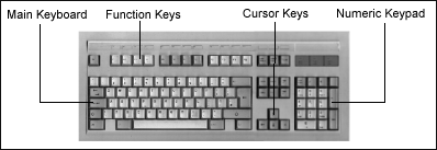
- Text input device that used mechanical contact closure, change in capacitance, and magnetic coupling
- Creates a unique code corresponding to the key pressed (ASCII or EBCDIC).
- Chording allows users to press several keys at once for rapid access to different commands
Valuator
- Provide scalar valuas based on potentiometers, volume and tone control dials on stereo equipment
- Usually rotary potentiomenters (dials) that can be rotated 330 degrees
- Continuous turn potentiometers can be rotated in either direction, no range boundary
- Linear potentiometers, which are bounded in range, are sometimes used in graphics systems.
Choice
Function keys are the most common form of choice devices. Other choice devices include buttons on a mouse
or puck. Choice devices are used to enter commands or select menu options.
Speech or Voice Recognition Systems
Conversa Web is a voice-enabled Web browser
that lets you travel anywhere on the Internet without relying on a mouse or keyboard
- Voice-activated Web browsing and navigation
- Speaker independent, no training required
- Intuitive say the links as they appear operation
- Voice-activated Saycon toolbar commands
- Voice-activated JPEG and GIF images
- Voice-activated Favorites List and online Help
Display Technologies
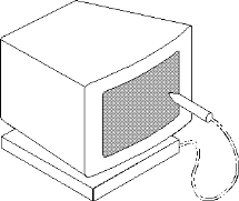
Cathode Ray Tube (CRT)
The most important component of the monitor is the Cathode Ray Tube (CRT) or picture tube. A CRT essentially
an oddly-shaped, sealed glass bottle with no air inside. It begins with a slim neck and tapers outward until it
forms a large base. The base is the monitors screen and is coated on the inside with a matrix of thousands of
tiny phosphor dots

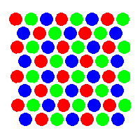
- Each group of 3 phosphor (RGB) dots make up a pixel
- The dot pitch is the distance between adjacent sets of red, green and blue dots
- Refresh rate for raster scan displays is at least 60 frames/second
- Stream of electrons from the heated cathode is accelerated twards the phosphor by 15-20K volts.
- A control grid voltage determines how many electrons are in the beam. High voltage, low electron count
- Light output of the phosphor decreases when the electron count in the beam decreases
- Focusing system concentrates the electron beam, so it can converge on a small point on the phosphor substrate
- Fluorescense is the light emitted by the phosphor atoms while struck by the electron beam
- Phosphorescence it the light "given-off" by the phosphor atoms when they return to their unexcited
state once the electron beam is removed.
- Persistence is "the time from the removal of excitationto the moment when phosphorescence has decayed
10 % of the initial light output". Peristence in most graphics displays is between 10 to 60 micro-senconds.
- Flicker develops when the refresh rate decreases to the point where the eye can no longer integrate
the individual light impulses coming from a pixel.
- Critical fusion frequency (CFF) is reached when the refresh rate is at a level where the picture stops
flickering, and fuses into a steady image. The higher the phosphor's persistence value the lower the CFF.
See: History
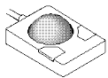
Shadow Mask Characteristics
A shadow mask is a thin metal plate located in front of the phosphor layer on the picture tube surface, carefully
aligned so that the electron beams for Red Green and Blue hit only one type of phosphor dot. Allow
each gun to irradiate only one color of phosphor.
- Phosphor dots arranged in triangular triad pattern
- RGB guns arranged in triangular pattern
- Guns are deflected together and converge on the same point
- One small hole for each triad
- In-line arrangement reduces image sharpness at the edges
- Masking of unnecessary electrons, avoiding overspill and resultant blurring of the final picture
- In high resolution displays triads are placed about 0.21 mm. centers (TVs 0.60 mm.)
- Beam diameter must be 7/4 times pitch to hit center of shadow-mask hole.
- As pitch decreases resolution increases
- Small pitch shadow mask are more fragile, can warp as result of heating from e-beam.
- Limits to CRT brightness, typically only 20% of the electrons in beam hit the phosphor substrate

 Delta pattern
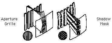
Trinitron vs. Traditional Shadow Mask Technologies
The Trinitron technology uses an aperture grille. This grille, designed with long, unbroken slits, allows
more light and color to reach the screen, resulting in purer and more colorful images. The Shadow Mask uses
a mesh-like, darker screen that creates a color shift ("doming") distortion and prevents color purity.
Trinitron tubes lay their colored phosphors down in uninterrupted vertical stripes. See figures below.
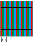 Aperture Grille (Trinitron)
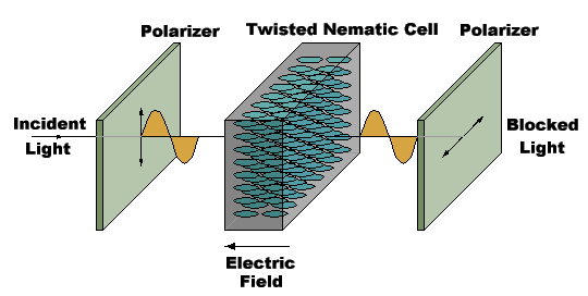
LCDs
Currently the most popular alternative to the CRT is the Liquid Crystal Display (LCD). LCDs are organic molecules
that, in the absence of external forces, tend to align themselves in crystalline structures. But, when an external
force is applied they will rearrange themselves as if they were a liquid. Some liquid crystals respond to heat
(i.e. mood rings), others respond to electromagnetic forces.
When LCDs are used as optical (light) modulators they are actually changing polarization rather than transparency
(at least this is true for the most popular type of LCD called Super-twisted Nematic Liquid crystals). In their
unexcited or crystalline state the LCDs rotate the polarization of light by 90 degrees. In the presence of an electric
field, LCDs behave like a liquid and align the small electrostatic charges of the molecules with the impinging
E field.

See: LCD vs. CRT Reference
New Display Technologies
- Laser Driven LCDs - Any size displays (i.e. 40 Diagonal screen), won't radiate electromagnetic energy, bright
displays easily readable in sunlight.
- Micro Displays
- From Inviso
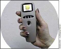
- A full-color display with 800-by-600-pixel resolution
- measures: inch across, an inch thick, and weighs under an ounce.
- Single-chip Optiscape II integrates a proprietary magnifying system when viewed from 2.5 inches, you see the
visual equivalent of a 19-inch monitor.
- PC World Article