Computer Graphics
CSE 5280 Viewing Fundamentals
References
The Stages of the Viewing Transformation
There are three conceptual stages in the 3D viewing process: clipping, projection and the transformation to
2D screen coordinates. This tutorial will cover the projection process.
Projection is the transformation of an n-dimensional coordinate system to an m-dimensional system (where m is less
than n). In computer graphics applications (such as CAD and virtual reality) the most common type of projection
is the transformation of 3D dimensional data to 2D data. This involves defining straight lines or `rays' called
projectors which through points on the object being projected and through the projection plane to form the 2D image.
The most commonly used projections are the parallel projection and the perspective projection.
Parallel Projections
In this, the projection lines are all parallel to each other. This means that the image formed on the projection
plane has the same relative dimensions as that of the original object (i.e. there is no concept of distance from
the viewer).Center of projection is at infinity and the direction of projection (DOP) for all points is
the same. This feature is important in applications such as CAD where it is important to preserve the object's
scale and shape. Parallel projections fall under 2 major categories:
- Oblique - Non-orthographics parallel projections. Projection-plane normal and the direction of projection differ.
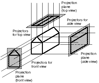
- Orthographic - The direction of projection is perpendicular to the view plane. When the direction of projection
is parallel to any of the principal axis, this produces the front, top, and side views illustrated
below. With any single projection we lose considerable information. Thus if we wish to display detailed information
about the object multiple projections is a must (see below):
Perspective Projections
This type of projection includes the concept of distance from the viewer by scaling the projected image of objects
by an amount relative to their distance from the view reference point. This transformation is determined by prescribing
a center of projection and a view plane. The view plane is determined by the view reference point
(VRP) and a view plane normal (VPN). The object point P is located in world coordinates
at (x, y, z). The problem is to determine the image point coordinates P(x', y', z'). Map points onto view plane
along projectors emanating from the center of projection (COP).
Pros - gives a realistic view and feeling for three dimensional form of object
Cons - does not preserve shape of object or scale (except where object intersects projection plane)
Different from a parallel projection because,
- parallel lines not parallel to the projection plane converge
- size of the object is diminished with distance
- foreshortening is not uniform.

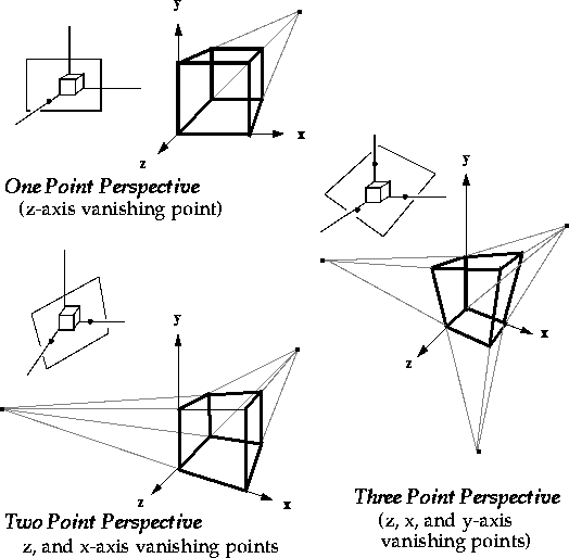
Number of Vanishing Points
Number of vanishing points = number of principal coordinate axes intersected by projection plane. One vanishing
point, one principal coordinate axis is intersected by projection plane, two vanishing points and two principal
coordinate axis intersected, and so on .....See figures below.
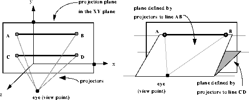
Vanishing Points and the View Point--1
- Lines AB, CD projected on XY plane.
- Projectors from the eye to AB and CD define two planes, which meet in a line which contains the view point,
or eye.
- This line does not intersect the projection plane (XY), because parallel to it
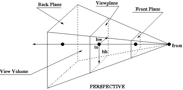
View Volumes
3D Viewing Process

Projection Plane
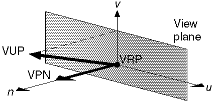
- Projection plane called the view plane in computer graphics
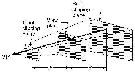
- Is defined by a point called view reference point (VRP) and a normal (a vector perpendicular to the
plane) called view plane normal (VPN).
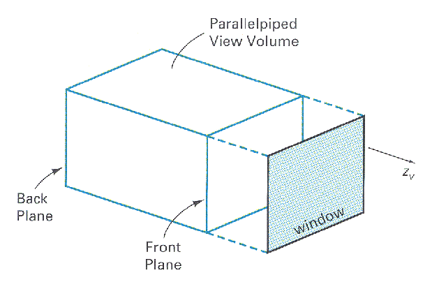
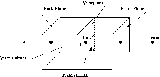
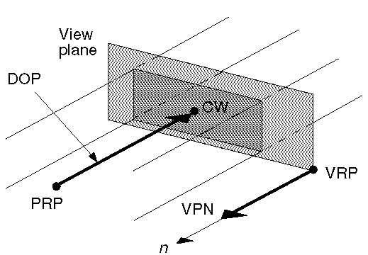
Parallel Orthographic Projection
- The VPN and the direction of projection are parallel.
- View volume is an infinite parallelpiped.
- When the focal point is far away the rays become nearly parallel to each other
- If the image plane is the XY-Plane, the orthographic projection of x, y, z is x,
y, 0. This and the other 2 cases the XZ and YZ-planes are called the front, top,
and side orthographic views. See projections illustration in Parallel Projections section.
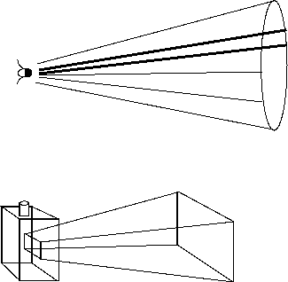
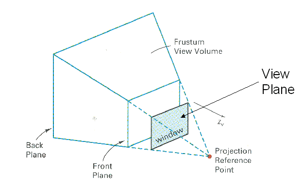
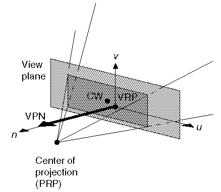
Perspective Projection View Volume
Semi-infinite view volume for perspective projection
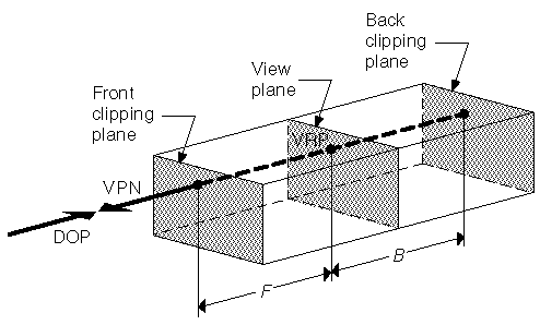
Clipping the View Volume for Orthographic Parallel Projection
Limiting view volume useful for eliminating extraneous objects
Limiting View Volume for Perspective Projections
- Removes objects too far from COP ("blobs")
- Removes objects too close to COP (would be distorted)
Summary
- Sometimes people ask "Why have multiple coordinate systems?"(x,y,z and u,v,n)
- Answer: Often want to see objects from multiple points of view. Need to rotate around center of object, not
of x,y,z world coordinate system.
- Adjusting the COP is hard (and making consequent adjustments in all other parameters is harder!)
- But rotating the coordinate system is easy.
- Because COP (or DOP) is defined in coordinates, as are the front and back clipping planes, and the window on
the view plane...
- Rotating rotates the entire view about the VRP. If the VRP is near the center of the window, hence near the
object of interest, this is convenient.


